In the following section I suppose you have installed Image Studio 1.1 and the TIGCC Tools Suite
on your PC. I suppose further that you know how to use the commandline tools from the TIGCC Tools
Suite especially how to use tool TTBin2Hex to convert a binary file into a textfile. It's not
really complicated. If you don't know the parameters of TTBin2Hex just run it without any
parameters by typing ttbin2hex and it will display it's usage text.
Ok, let's jump into the details. That's why we are here, isn't it?
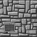
Suppose we have the following image (BMP file) containing already 6 textures which we want to
use with the FAT-Engine:
It doesn't really matter if your inputfile is already in grayscales, but doing the color to grayscale
conversion in a sophisticated graphics program like PaintShop or similar is always a good idea. Additionally
it is a good idea to convert more than one texture at once. Why? Well, if you convert textures one by one
it becomes a painful task that the overall lightness/darkness of your textures fit together. Reducing
colored textures to only 4 grayscale values (including white and black) rips off many details and it looks
really ugly if similar textures (like the ones in the above example) which will be drawn side by side won't
fit in there overall lightness/darkness.
The first step in converting the textures for use with the FAT-Engine is to load the BMP-File with
Image Studio. Adjust the contrast of the finally result using the sliders supplied by ImageStudio and
when you are pleased with the result export the picture as Binary File (File->Export). Make sure that checkbox
RLE compressed is NOT checked and that the image mode is set to Standard Grayscales (Image->ImageMode).
IMPORTANT NOTE: ImageStudio can only convert pictures up to 240x128 pixels. Converting 6 textures arranged
in a 2x2 grid is therefore the maximum number of textures you can convert in one step.
The next step in preparing textures for the FAT-Engine is to run Tool FixTex64 (bin/fixtex64.exe from the FAT-SDK)
on it. Call FixTex64 without any commandline parameter and you will get its usage text. FixTex64 performs a 90
degrees to the left rotation of each texture in the inputfile and arranges the textures to be below each other.
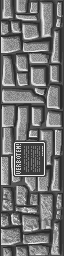
The binary data of our original input file will look like this after running FixTex64 on it:
Suppose we have exported our example image into file texsample.bin, than we will call FixTex64 this way:
fixtex64 texsample.bin texnew.bin 2 2
The last two parameters tells the tools how the textures are aligned in the inputfile. In our case they are aligned
in a 2x2 grid.
Ok - Are you still here? We have now finished two out of five steps. To generate a FAT standard texture format file
we need our binary data as plain text. If you don't know anything about the FAT standard texture format it will be a good
idea to read the following document yet:
FAT Standard Texture Format (including TexMaker Documentation)
Especially take a look on the docs about tool TexMaker.
Still here? Well, then you are quite stubborn .... ;-) ... Let's proceed converting our outputfile generated by FixTex64
into a plain text file using TTBin2Hex from the TIGCC Tools Suite. Suppose you have named the output of FixTex64 converted.bin.
The following line will convert this binary file into a plain textfile:
ttbin2hex -c 8 -b4 converted.bin mytex.txt
When you open mytex.txt in a texteditor you will see that it contains many, many hexnumbers. These are our textures in a
textform representation. We don't really care about these numbers. They are just input for TexMaker. Step number 4 is to
add some information for TexMaker to the head of mytex.txt. If you don't know anything about TexMaker just copy the
following block to the beginning of mytex.txt:
TEXCONFIG TEXTURE1
STRIP1 start,     start+512,     NULL, NORMAL
STRIP2 start+128, start+512+128, NULL, NORMAL
STRIP3 start+256, start+512+256, NULL, NORMAL
STRIP4 start+384, start+512+384, NULL, NORMAL

TEXCONFIG TEXTURE2
STRIP1 start+1024,     start+1024+512,     NULL, NORMAL
STRIP2 start+1024+128, start+1024+512+128, NULL, NORMAL
STRIP3 start+1024+256, start+1024+512+256, NULL, NORMAL
STRIP4 start+1024+384, start+1024+512+384, NULL, NORMAL

TEXCONFIG TEXTURE3
STRIP1 start+2048,     start+2048+512,     NULL, NORMAL
STRIP2 start+2048+128, start+2048+512+128, NULL, NORMAL
STRIP3 start+2048+256, start+2048+512+256, NULL, NORMAL
STRIP4 start+2048+384, start+2048+512+384, NULL, NORMAL

TEXCONFIG TEXTURE4
STRIP1 start+3072,     start+3072+512,     NULL, NORMAL
STRIP2 start+3072+128, start+3072+512+128, NULL, NORMAL
STRIP3 start+3072+256, start+3072+512+256, NULL, NORMAL
STRIP4 start+3072+384, start+3072+512+384, NULL, NORMAL


BINDATA

LABEL start

// here comes the numbers ....
Now run tool TexMaker (bin/texmaker.exe from the FAT-SDK) on mytex.txt and you will have generated
a FAT texture format file holding our 4 input textures.
Let's take a look on one of the TEXCONFIG blocks and what all these settings means:
TEXCONFIG  TEXTURE1
STRIP1 start,     start+512,     NULL, NORMAL
STRIP2 start+128, start+512+128, NULL, NORMAL
STRIP3 start+256, start+512+256, NULL, NORMAL
STRIP4 start+384, start+512+384, NULL, NORMAL
Internally the 64x64 pixel textures of the FAT-Engine are organized as 4 strips each 16 pixels wide.
Each TEXCONFIG block consists of 4 STRIPn definition lines (STRIP1/STRIP2/STRIP3/STRIP4) which tells
TexMaker where the data for each strip is located.
The name right beside the keyword TEXCONFIG is
an optional name for the TEXCONFIG block. If you want TexMaker will generate a C header file for you
containing these names as defines like "#define TEXTURE1 0". It make sense to use these defines
afterwards in your program instead of using index numbers like 0 directly.
Consider that the data for each grayscale plane takes 512 bytes. Each strip consists of data
for the lightplane and data for the darkplane each 128 bytes long. A STRIPn configuration consists of
the following fields:
offset to lightplane data [comma]
offset to darkplane data [comma]
offset to maskdata [comma]
mirror field content
TexMaker is able to use label for the offset. In our example we only have defined one label called
start at the beginning of the BINDATA. Well, this is not quite useful, but should only demonstrate
the usage of label. If you make texture files by your own you can use as much labels as you want
(up to 2048).
Take a look on the first STRIPn line: This line tells TexMaker that the data for the lightplane
starts at offset start (our label), the data for darkplane is at start+512, there is NO
maskdata (keyword NULL) and this strip should be displayed normally (mirrorfield=NORMAL).
Due to the conversion done by FixTex64 previously in the "conversion chain" the data of our
textures in the BINDATA block are arranged like that:
Texture 1 - lightplane data [512 bytes long]
Texture 1 - darkplane data [512 bytes long]
Texture 2 - lightplane data [512 bytes long]
Texture 2 - darkplane data [512 bytes long]
Texture 3 - lightplane data [512 bytes long]
Texture 3 - darkplane data [512 bytes long]
Texture 4 - lightplane data [512 bytes long]
Texture 4 - darkplane data [512 bytes long]
It should be now obviously where all the numbers in the TEXCONFIG blocks came from, isn't it?